Sensing for Science - Level 3 Display
Displays
So far in this series we have used the Serial Monitor to display data. But if we want
to take our circuit out in the field to collect data, it would be better to not have
to carry the computer along. It solve this problem we can add a display to our circuit.
There are many different types and sizes of displays we can purchase for our Arduino.
We are going to use the liquid crystal display (LCD) for our display. This display
will allow us to have 32 (2 rows of 16 characters) characters. We will construct the
LCD use two different methods.
Circuit #1
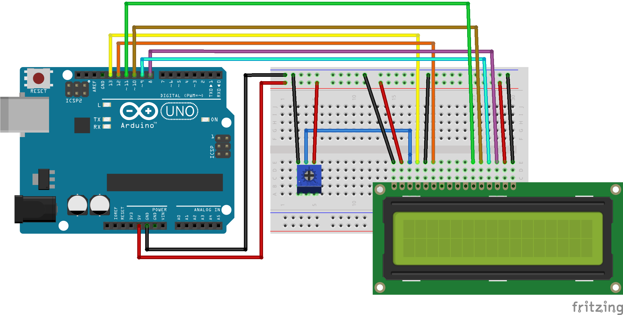
Let’s start with the basic functionality of the LCD. Looking at the diagram below
wire up the LCD screen. There are a lot of wires, if you mess up it is ok. This is
a great exercise in troubleshooting your wiring.
Code #1
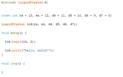
Once you have the LCD screen wired up, we can write some code to test the circuit. Copy the code below and upload it to the Arduino board.
Troubleshooting
My LCD is not lighting up -> check you wiring connects-> check for broken wires
My LCD is lighting up but I don’t see anything-> turn the knob on potentiometer to
change contrast-> check wiring
My LCD screen has a bunch of mumbo jumbo-> reset the Arduino board->check wiring
Code #2
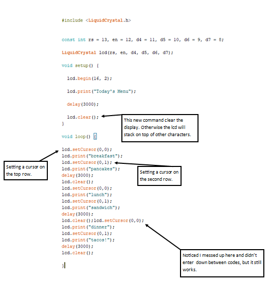
Now that you have successfully sent data to the display, lets explore how we can use the LCD. We are going to make a revolving meal menu and a temperature display. These are just a few things you can use displays with. There are more uses and different types of displays out there and they all work pretty much the same. This next section of code to copy will produce a revolving menu a dining hall. This code should start up and display “today’s menu”) and then start looping through the different meals.
Code #3
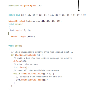
This next code allows us to send data to the lcd from the serial monitor. It almost
like sending instant messages, but it is only to the lcd. Copy the code below and
follow the instructions. This code can also be found in the file->examples->liquidcrystal->serialdisplay.
If you use the example code, make sure you make changes to the pin outs for the lcd.
Upload the code to your Arduino board and open the serial monitor. At the top of the
serial monitor is a command bar where we can type in. Type “test” and click send.
You should see “test” show up on your lcd screen. Remember we can only have 16 characters
and spaces count as a character.
Circuit #2
Now that we have the basic functionality of the LCD screen down, lets look at a way
to simplify the wiring. We are going to use the I2C (inter-integrated circuit ) adaptor
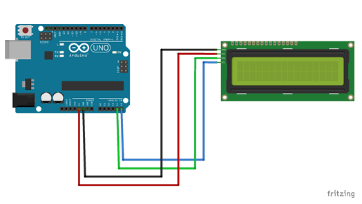
for the LCD to condense the wires down to 4. To start find your I2C adaptor and attach
it to your LCD. Next create the circuit below.
Once you have the circuit built, let’s look at the first code we are going to use.
When using I2C we need to find the address of the device. Most devices you purchase
will come with an address labeled. But what if you need to find the address? Well
there is a code for that prebuilt in the LiquidCrystalI2C library, which is not included
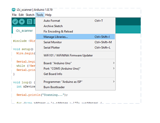
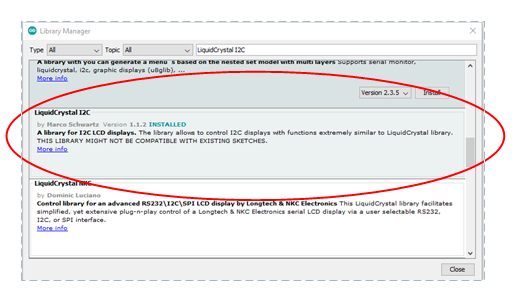
in our Arduino library. We will need to install this library first. In Arduino go
to Tools->manage libraries. When the library manager opens, search for “liquidcrystal
I2C”. You will need to scroll down a bit and find the right library by Marco Schwartz.
Click the install button and wait for the library to be installed and close out of
the library manager.
Scanning for Address
Find the i2c scanner under File->Example->Wire->ic2_scanner. Open that sketch and
upload it to your board. Once the code is uploaded, open the serial monitor and watch
the code do its job. You will be given a hex address that you should right down, we
will be needing it later. Mine for this device is 0x27. In more complex circuits we
would need to change addresses of devices but that is outside the scope of what we
are doing for this series.
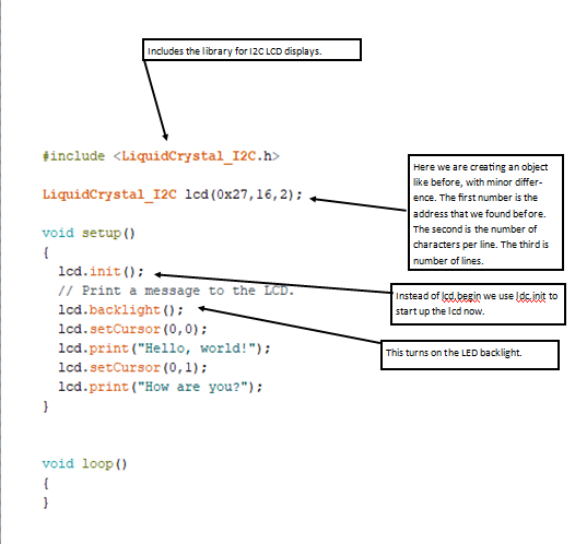
Now that we have the device address we can start playing with the lcd again using
I2C adaptor. Most of the code will still be the same as before with a differences.
Lets look at the code on the next page and see what is different. This code can be
found in examples under the LiquidCrystal I2C library labeled hello world. You will
need to make some changes to the example code to work with our display of 12x2. The
example uses a 20x4 display.
Code #1
As you can observe, with only a few differences, the lcd still functions the same
, but with only 4 wires. This will help down the road when we start adding more components
and will need to have pins available to us.
Circuit #3
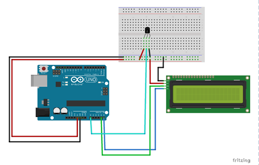
Now that we are comfortable with the lcd screen, let’s add a sensor to the project. We are going to create a temperature reader. We will be using TMP36 sensor. These are a cheap but pretty precise sensor. If you look at it with the flat side towards you the left pin needs to be connected to 5v. The middle pin needs to be connected to A0. The right pin needs to be connected to ground. Now if you have the 5v and ground flipped you will know, the sensor get very hot when this happens and will burn you if you are not careful. When you power up the circuit and you feel heat, power down right away and flip the connections. Use the diagram below to help with construction.
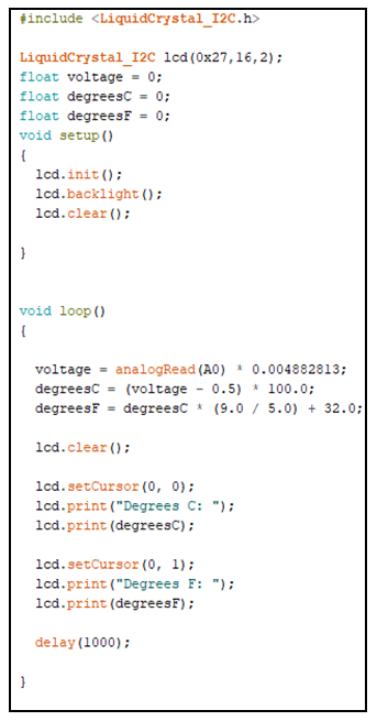
One of the things you might notice is that we can use arithmetic in our code. We use arithmetic in this project to convert the voltage reading from the A0 pin to a value we can understand (temperature). You may notice that we can print variable values into the LCD.
Code #1
Troubleshooting
• Sensor is very hot-> gnd and 5v needs to be flipped
• LCD is showing jumbo->check connects-> check code->reset board
Going further
• Add another temperature scale to display
• Can you change code to get a more accurate reading?
• How could you waterproof the temperature sensor?

